Air and fluid temperature sensors operate by
changing their electrical resistance as the temperature changes. Due to the
mechanics of
reading these sensors a stock sensor cannot be shared between the vehicles
engine management system and the Zeitronix Zt-2 Wideband system. Each system
must have its own sensor.
I. Temperature Sensor Installation
II. Multiple Sensor Installation
III. Temperature
Sensor Installation for User1 Input
I. Single Temperature Sensor Installation
Temperature sensors can be used to monitor oil, transmission,
water and air temperatures.
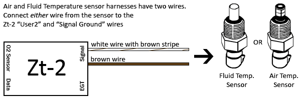
Air and fluid temperature sensors have two wires. Wire
colors may be black and orange, or black for both wires. The two wires are interchangeable
and either wire can be used when making the connections in the instructions below.
|
- Connect a temperature sensor wire to the Zt-2 Signal
Harness "User2" input.
This wire is a white wire with a brown stripe (pin
8).
- Connect the second temperature sensor wire to the Zt-2 Signal
Harness "Signal Ground" wire.
This wire is brown (pin 11).

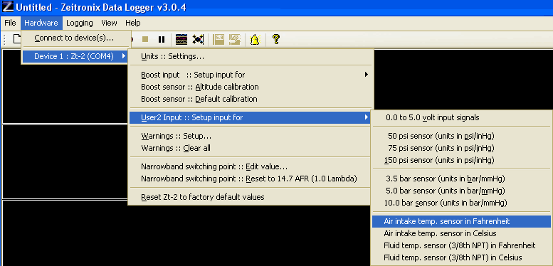
- Setup the Zt-2 "User2" input. By
default the "User2" input will read a voltage.
To change this to a temperature select either Fahrenheit or Celsius
temperature readings from the following menu:

|
II. Multiple Sensor Installation
Two methods exist for attaching more than one temperature sensors to the
Zeitronix Zt-2. Method 1 involves using a switch to switch between the
sensor connected and is detailed below. The benefit of this method being
the value is passed on to any displays. Method 2 involves using a resistor
and software to convert from a voltage to a temperature value using the User1
input. Details on
Method 2 available here.
By using an optional switch Zt-2 inputs can be given "double duty" helping you
get more information and the best performance from your vehicle. Common uses
for this technique include monitoring oil and fuel pressure, measuring
intercooler efficiency, or monitoring an additional oil, transmission, water or
air temperature.
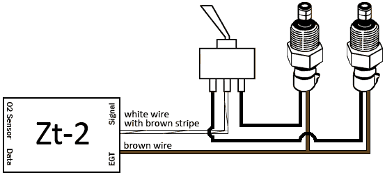
In the example below two air temperature sensors are connected to the Zt-2 User2
input. This configuration will work equally as well using an air
temperature sensor and a fluid temperature sensor or by using two fluid temperature
sensors.
A similar setup as the one below can be used to monitor
oil, fuel, and MAP pressures using the Boost input (orange wire pin 4) or the
User2 input (brown-white wire pin 8). To do this use two identical
pressure sensors. Connect the pressure sensor signal outputs (green wires)
to the switch and the ZT-2 input to
the center connection on the switch. Setup the Boost or User2 input in the software
for the sensor type you are using. The two pressure sensors can be powered
by the Zt-2 Boost sensor +5V power, yellow wire (pin 6), and grounded to the
brown signal ground wire (pin 11).
Example:
Air and fluid temperature sensors have two wires. Wire colors may be black and orange, or black
for both wires. The two wires are interchangeable and either wire can be
used when making the connections in the instructions below.
|
- Connect one of the wires from each
temperature sensor to the the Zt-2 Signal Harness "Sensor Ground" input.
This wire is the brown wire (pin 11).
- Connect the second wire from each
temperature sensor to the outer connection points on the switch.

- Connect the Zt-2 Signal
Harness "User2" wire (pin 8) to the center connection point on the
switch.
This wire is white with a brown stripe.
- Setup the Zt-2 "User2" input. By
default the User2 input will read a voltage.
To change this to a temperature select either Fahrenheit or Celsius
temperature readings from the following menu:

|
III. Temperature Sensor Installation for User1
Input
Temperature sensors can be attached to the Zt-2 User1 input
with the help of a resistor and 5 volt power.
See the User1 Temperature Sensor Setup
page for details.
|
|
The air and fluid temperature sensors can be found on the Zeitronix
order page. |

